
Change the Chemistry.Change the World!
An integrated botanical extraction and purification platform built on non-flammable surfactant chemistry.
Explore the advantagesWith the potential to make botanical processing
Reduce
unit operations
Each piece of equipment, each process, is another point of failure that will cost time, money and potentially, customer relationships.
- No ultra-freezers
- Process without cryogenic cooling
- No winterization
- Leave fats and waxes behind
- No drying rooms
- Process fresh, wet plants
- No filtration
- Leave chlorophyll and color behind
- Simpler logistics
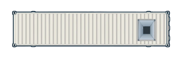
- Extract on-farm in Conex units
- 99+% Purity
- Direct crystallization
Fewer unit operations. Less equipment and facility overhead. Lower operational expenses.
Lower costs.
More possibility.
Reduced unit operations means reduced Capital Expenses and debt. Debt service can cost millions every year, and it comes directly out of, what could be, profit.
Lower construction costs
Eliminate C1D1 extraction rooms, enabling on-farm extraction
Lower equipment costs
Avoid the need for explosion-proof extraction equipment
Lower regulatory costs
Reduce municipal and state costs associated with flammable-solvent extraction
Reduce time to become operational
Lower insurance costs
Reduce fire and explosion risk by eliminating flammable extraction solvents.
Manufacturers that use similar methods live with compressed margins.
We think we have the answer to open up profitability for your natural compounds.
Remove flammability and open up opportunities for “green”
Our upstream process leverages surfactant chemistry. We’ve patented it! Our surfactants are non-flammable and waste-streams are biodegradable. Effluent waste is primarily NPK (nitrogen, phosphorous, potassium), the components of fertilizer! And our process is efficient.
Because of these advantages, we expect many municipalities to green-light on-farm extraction where it was previously prohibited. Think of the savings in transportation costs and improved product quality.
Surfactant extraction is aqueous
No drying!
Process fresh and wet… or dry, as you choose
The cost of drying
Recently a cannabis oil manufacturer petitioned their capital group for $5M for on-farm drying operations to mitigate these problems. Debt is expensive, surrendered equity is value lost; our process saves money!
Extraction, close to the crop.
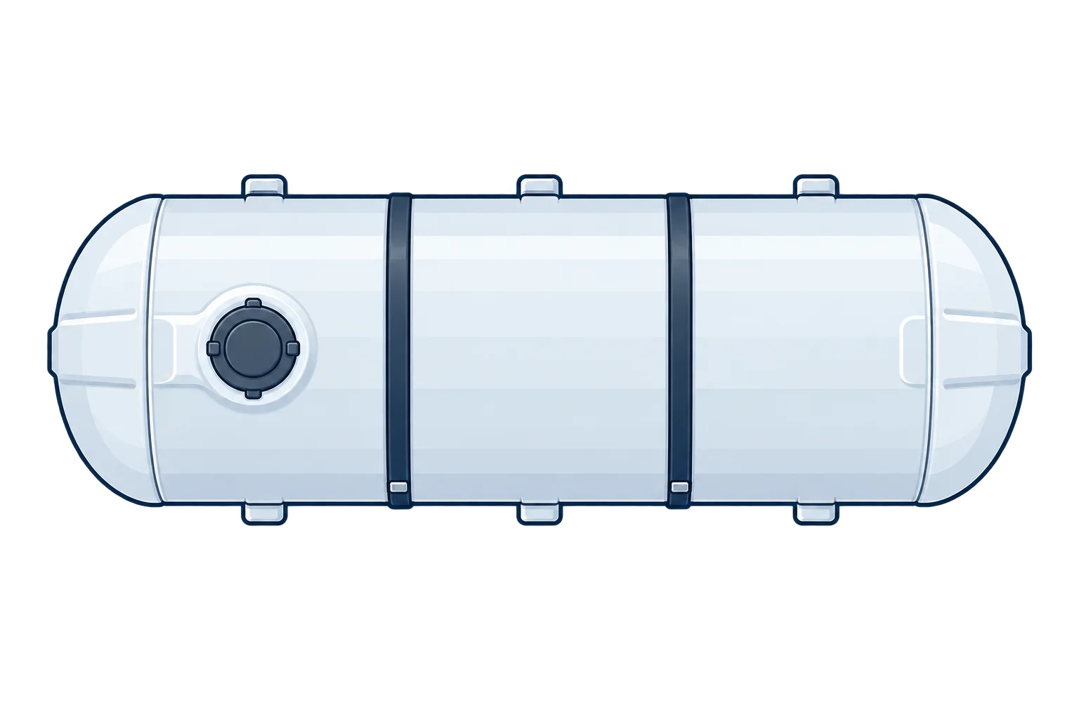
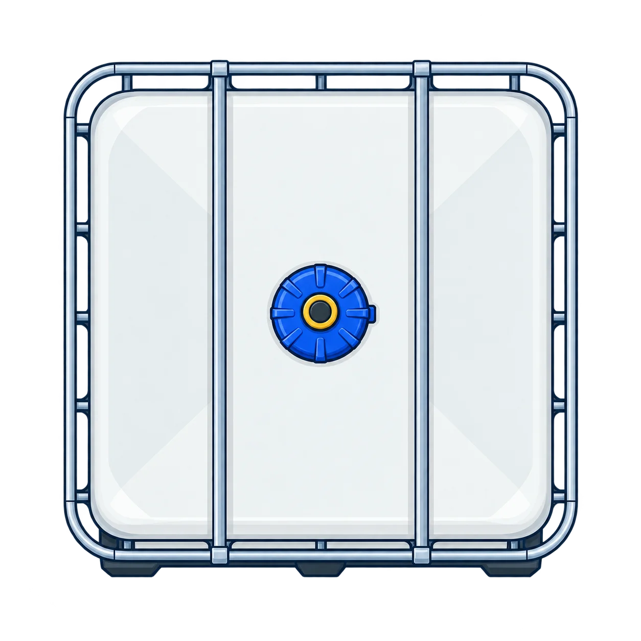
Prepare the biomass. Feed directly into the Extractor Conex.
- Biomass
- Process liquid
- Extract oil
- Sifting rejects

What exactly
is our process?
Upstream
From biomass to recovered extract oil
- Biomass
- Process liquid
- Extract oil
Harvest. Silage for more than a year if needed, with little loss
Matching letters connect continuing streams. Hover, focus or tap equipment and connectors for details.
- 01
Prepare
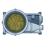
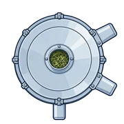
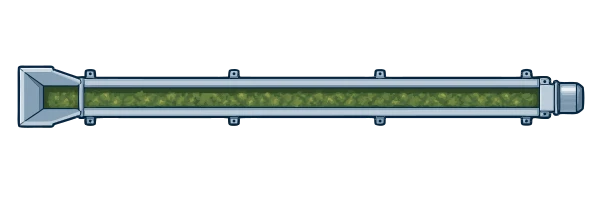
Macerate and sift the biomass. Convey accepted material to the mixer.
Hammer mill: macerates the biomass before sifting.SWECO circular sifter: separates accepted biomass from rejects.Inclined conveyor: carries accepted biomass to the cone mixer.To Extract: accepted biomass continues to the cone mixer.Hammer mill: macerates the biomass before sifting.SWECO circular sifter: separates accepted biomass from rejects.Inclined conveyor: carries accepted biomass to the cone mixer.To Extract: accepted biomass continues to the cone mixer. - 02
Extract
Wet with our emulsion, then squeeze. Pressing separates extract-bearing liquid from wet biomass.
Cone mixer: wets and agitates biomass with surfactant emulsion.Progressing-cavity pump: transfers wetted biomass to the screw press.Screw press: separates extract-bearing liquid from pumpable wet biomass.From Prepare: accepted biomass enters the cone mixer.To Recover: extract-bearing liquid joins recovered liquid at the lamella separator.To Recover: pumpable wet biomass continues through a cavity pump and liquid-solid separator.Cone mixer: wets and agitates biomass with surfactant emulsion.Progressing-cavity pump: transfers wetted biomass to the screw press.Screw press: separates extract-bearing liquid from pumpable wet biomass.From Prepare: accepted biomass enters the cone mixer.To Recover: extract-bearing liquid joins recovered liquid at the lamella separator.To Recover: pumpable wet biomass continues through a cavity pump and liquid-solid separator. - 03
Recover
Recover liquid from the separator and screened holding bin. Combine it with press liquid at the lamella separator for oil–water separation.
Cavity pump: transfers pumpable wet biomass from the screw press.Liquid-solid separator: recovers liquid from the wet biomass.Holding bin with a screened bottom: collects biomass and recovers remaining liquid.Lamella separator: separates oil from the combined press liquid and recovered liquid.Oil collection vessel: collects the recovered extract oil.From Extract: pumpable wet biomass from the screw press enters the cavity pump.From Extract: extract-bearing liquid from the screw press joins recovered liquid before oil–water separation.To Downstream: collected extract oil continues to liquid-liquid extraction.Cavity pump: transfers pumpable wet biomass from the screw press.Liquid-solid separator: recovers liquid from the wet biomass.Holding bin with a screened bottom: collects biomass and recovers remaining liquid.Lamella separator: separates oil from the combined press liquid and recovered liquid.Oil collection vessel: collects the recovered extract oil.From Extract: pumpable wet biomass from the screw press enters the cavity pump.From Extract: extract-bearing liquid from the screw press joins recovered liquid before oil–water separation.To Downstream: collected extract oil continues to liquid-liquid extraction.
To downstreamRecover crude oil with some impurities (color compounds, surfactant)
Downstream
From crude oil to crystals
Separate the target. Form the crystals. Wash and finish.
- Extract / raffinate / recovery
- Heavy phase / Wash 1
- Wash 2
- Crystals / slurry
- Heating
- Cooling
- Vacuum
Matching letters connect the stages. CS / CR connect cooling supply and return. Tap or focus equipment and connectors for details.
- 04
Separate
Extract the target chemical into our “green” crystallization carrier.
The centrifugal contactor separates the loaded heavy phase from the raffinate. Heating supports this step.
Extract oilHeavy phaseHeatLoaded heavy phaseRaffinateExtract-oil supply: recovered extract oil from upstream supplies the light phase to the contactor.Metering / transfer pump: moves liquid between process stages.Heavy-phase supply: the unloaded crystallization carrier receives the target during liquid-liquid extraction.Metering / transfer pump: moves liquid between process stages.Centrifugal contactor: brings the light and heavy liquid phases into contact, then separates them.Metering / transfer pump: moves liquid between process stages.Heater bath: circulates heating fluid through the contactor heating circuit, separately from the process liquids.From upstream Recover: collected extract oil supplies the light phase.To Crystallize: loaded heavy phase carries the target to the crystallizer feed manifold.To Surfactant recovery: raffinate leaves the bottom outlet for the wiped-film evaporator. - 05
Crystallize
Form fine crystals of the target compound in a controlled process.
Chilled Wash 1 rinses each crystallizer and carries its crystals to the shared filter. One central chiller serves both jackets and the wash coolers.
Wash 1Chilled Wash 1Loaded heavy phaseC01C02Crystal slurry + crystallizer rinseCentral chillerWash 1 supply: unloaded heavy phase is cooled before rinsing the crystallizer and carrying its crystals to filtration.Metering / transfer pump: moves liquid between process stages.Countercurrent cooler: cools the wash stream through a separate coolant jacket. Cooling fluid does not mix with the wash liquid.Crystallizer C01: forms crystals in the loaded heavy phase. CrystalClear™ selects its fill, chilled Wash 1 rinse and discharge. One batch at a time enters the shared filter.Crystallizer C02: the second batch vessel shares the feed manifold, Wash 1 cooler, central chiller and filter with C01. Fill and discharge are selected sequentially.Central chiller: supplies cooling fluid to both crystallizer jackets and both wash coolers. CS is cooling supply; CR is cooling return.Cooling supply from the central chiller. This utility stays separate from process liquid.Cooling return to the central chiller. This utility stays separate from process liquid.Chilled Wash 1 from the shared cooler. R connects the rinse supply to each crystallizer; only the selected batch is rinsed and discharged.From Separate: loaded heavy phase carries the target compound to the shared feed manifold. CrystalClear™ selects the next crystallizer for filling.CrystalClear™ selects C01 for filling. The shared manifold directs the feed to one selected vessel at a time.Chilled Wash 1 from the shared cooler. R connects the rinse supply to each crystallizer; only the selected batch is rinsed and discharged.Rinse C01 with chilled Wash 1 after crystallization, carrying crystals to the shared filter.Discharge C01 after crystallization. Batches discharge sequentially: one batch at a time reaches the shared filter.Cooling supply from the central chiller. This utility stays separate from process liquid.Cooling return to the central chiller. This utility stays separate from process liquid.CrystalClear™ selects C02 for filling. The shared manifold directs the feed to one selected vessel at a time.Chilled Wash 1 from the shared cooler. R connects the rinse supply to each crystallizer; only the selected batch is rinsed and discharged.Rinse C02 with chilled Wash 1 after crystallization, carrying crystals to the shared filter.Discharge C02 after crystallization. Batches discharge sequentially: one batch at a time reaches the shared filter.Cooling supply from the central chiller. This utility stays separate from process liquid.Cooling return to the central chiller. This utility stays separate from process liquid.To the shared Filter & wash stage: crystal slurry and crystallizer rinse, one selected batch at a time.Cooling supply from the central chiller to both crystallizer jackets and both wash coolers.Cooling return from both crystallizer jackets and both wash coolers to the central chiller. - 06
Filter & wash
Retain the crystals. Draw liquid through the filter, then wash the crystal cake with chilled Wash 2.
Collect heavy phase and Wash 1 together. Switch the collection path for Wash 2, keeping the two recovery streams separate.
Wash 2Chilled Wash 2VacuumWashed crystalsHeavy phase + Wash 1Wash 2Crystal slurry + rinseWash 2 supply: a separate cooled wash is applied directly to the crystal cake in the filter.Metering / transfer pump: moves liquid between process stages.Countercurrent cooler: cools the wash stream through a separate coolant jacket. Cooling fluid does not mix with the wash liquid.Vacuum filter: retains the crystal cake above the frit. Liquid passes below it; Wash 2 washes the cake directly.Vacuum pump: draws from the space below the filter frit, separately from the liquid collection outlet.Crystal collection jar: collects washed crystals from the filter for analysis.Heavy phase + Wash 1 receiver: collects the first filtrate fraction for its recovery system.Wash 2 receiver: collects the second wash separately for its own recovery system.Cooling supply from the central chiller. This utility stays separate from process liquid.Cooling return to the central chiller. This utility stays separate from process liquid.From Crystallize: crystal slurry and crystallizer rinse enter the filter.Filtrate selection changes with the wash stage. Heavy phase and Wash 1 collect together; Wash 2 is collected separately. The selector directs each fraction to its collection vessel.Heavy phase plus Wash 1 continue to their recovery system.Wash 2 continues to its separate recovery system.
Analyze.Confirm the finished ingredient.
99%+ purityAchieved in cannabinoid crystalline isolates.
Surfactant recovery
Recover process fluid and collect terpenes from the raffinate.
Evaporate and condense the recoverable process fluid for collection and return. Collect raffinate concentrate and recovered terpenes separately.
Two-crystallizer process · equipment and connections shown schematically
CrystalClear™Control crystallization.
Automate your process.
CrystalClear is our proprietary system for controlling equipment and automating crystallization workflows.
It coordinates automated actions and operator steps, monitors the process, and preserves run records for review. Methods remain separate from equipment configuration, so they can adapt to supported hardware.
Define the method
Organize the sequence, timing and operator decisions. Check the workflow in simulation before using physical equipment.
Your method. Adaptable equipment.
Keep process logic separate from equipment configuration. Adapt methods to supported hardware while coordinating automated equipment and manual operations.
Guide the run
Coordinate configured equipment and operator prompts while monitoring the process. Keep the next step clear as the method progresses.
Preserve the run
Keep method settings, events and process trends together to support review and inform the next experiment.

Not just cannabis.
We look forward to matching our chemistry to your natural products
- Nutraceuticals
- Natural flavors
- Natural pharmaceuticals
- Cosmetic ingredients
- Natural cleaning products
… and many more!
Our first work was to extract CBDA and THCA in pure crystalline form. Since then our chemistry has expanded and so has our mission:
Our mission is to replace every other method of extraction and crystallization for hundreds of compounds by 2030.
Contact us to determine if our chemistry will save money on your commercial target materials
Don’t wait, contact us before your competition does!